|
13:12:15 - 04/19/2024
How To: Timing Chain and Tensioner
By Larry of J & J Auto
Discuss this
with the author
Ready to have some FUN.!!!
I am not going to go in to great detail with the first few things
you need to do, there are to many other important details.
Besides just replacing the timing chain and adding the tensioner
to solve the chain rattle that the 3.9 has, I will also be showing
you how to degree your cam in for Max Performance and a
discussion about overlap, the scavenging effect it has, exhaust
inertia and injector synchronization.
All this needs to be taken into consideration to get the best
results and performance out of your motor.
Disconnect your Neg. batt cable and be sure it will not move and
make contact with the post.
You need to remove the clutch fan and the radiator shroud and
drain as much coolant out that you can. Find a piece of
cardboard or an old blanket to protect the radiator it don't take
much to poke a hole in it and it can happen very easy. 20/20
foresight
Take a breaker bar and 19/32 socket put it on the belt tensioner
bolt and pull on it to release the tension and remove the belt,
be sure you have a diagram of how the belt goes on or make a
mental note or draw a picture so you can easily reinstall the belt.
Remove the water pump, disconnect the lower radiator hose and
remove the clamp from the bypass hose that comes off the rear
of the pump assembly, I will list the torque for all the bolts later.
Now is the best time to replace the bypass hose.
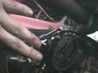
Unbolt the crank pulley from the vibration damper and remove the
32mm bolt in the center with either a 1/2 impact or a breaker bar
a few good wacks with a hammer will usually get it.
Using a steering wheel puller or damper puller, pull the damper
off the crank shaft. (DO NOT USE A GEAR PULLER) and grab
the outside of the damper to remove it you will destroy it. Use
a washer or a nut that is just smaller than the crank dia 1 1/2"
for the center bolt of the puller to hit, the nodular iron cranks
are not as hard as the old forged steel and you do not want
to damage the threads.
Before you pull the damper be sure its lined at TDC compression
stroke, check the dist rotor to be sure its aimed at the #1 plug wire
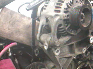
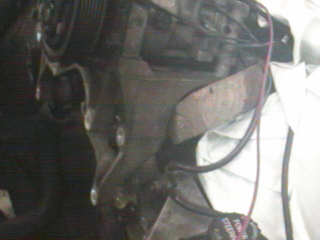
You need to unbolt the Alt/Air bracket and lift it up about 3 to 4"
to remove the timing cover, There are 6 bolts on the front 1 is
behind the idler pulley and you need to remove the idler to
remove the bolt. On the right side top of motor there is a bracket
with 3 bolts remove this. Left side top there is a strap remove
the bolt on the far end from the intake manifold. Now lift the whole
unit and block up with 2 short 2X4's
Now remove the timing chain cover and we are ready to begin
replacing the chain and adding the tensioner. There are also
2 bolts you need to remove from the front of the oil pan. Be
sure to remove these bolts. pull the top out first because you
need to lift up the cover to get the bottom out.
Remove all the spark plugs from the motor (ALL OF THEM)
you will need to be able to rotate the motor freely.
Put the big bolt back in the crank and line up the marks on
the existing sprockets, remove the dist cap and be sure
the rotor is pointing at or near the #1 plug wire, just set it
back on for now be sure the rotor don't hit and break while
you are turning the motor over. we will deal with setting
the injector sync later. DO NOT use the cam bolt to rotate
the motor. remove the washer from the bolt before you screw
it in this way the crank sprocket will come off over the bolt.
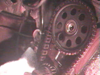
Now remove the cam sprocket bolt and remove the chain
and sprockets, if you turn the crank while doing this just
line it back up before you completely remove them.
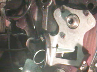
Remove the existing backing, thrust plate from the motor
by taking the 3 1/2" bolts out.
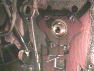
Clean the bolt holes and the bolts with either starting
fluid or carb cleaner, than blow the bolts and holes out
with compressed air, put 2 drops of blue (BLUE) removable
lock tight on the bolts install the new plate with the tensioner
on the motor and torque the bolts to 17 foot pounds
Check the end play .002 to .013
put a rag over the opening in the oil pan and clean the gasket
surface at this time.
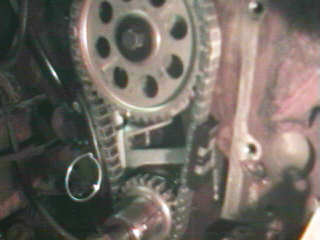
Install the new chain and sprockets and the cam bolt, do
not tighten the cam bolt yet just snug it down a little.
Making sure the marks on the sprockets are aligned properly.
if you need to use an off set key you will need to remove
the cam sprocket to get the crank sprocket off to change the key.
clean the hole and bolt and use 2 drops of blue locktight and
torque the bolt to 50 foot pounds when done.
put a rag over the opening in the oil pan and clean the gasket
surface at this time.
Install the new chain and sprockets and the cam bolt, do
not tighten the cam bolt yet just snug it down a little.
Making sure the marks on the sprockets are aligned properly.
if you need to use an off set key you will need to remove
the cam sprocket to get the crank sprocket off to change the key.
clean the hole and bolt and use 2 drops of blue locktight and
torque the bolt to 50 foot pounds when done.
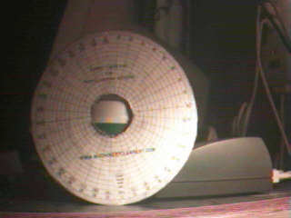
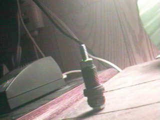
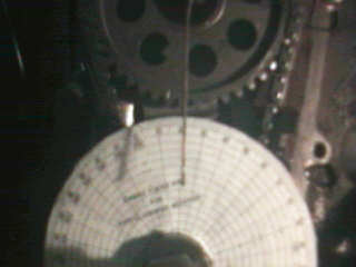
You also need to make a pointer and attach it to the motor
having the wheel near the 0 with the pointer on 0 I just used
a piece of welding rod a short bolt and washer and made a
pointer and lined it on 0

Now you need to make a piston stop to find true top dead center.
Take an old spark plug with a pliers or vise grip bend the ground
electrode back and forth until it breaks off. Break the porcelain part
of and take a punch and remove all of it from the plug until you
have a hollow plug be sure you do not damage the threads you
will need to screw it in the #1 plug hole. Use a 1/4 bolt and nut
and install it in the hollow plug. tighten it and be sure the peaks
of the nut do not stick out beyond the threads (center)
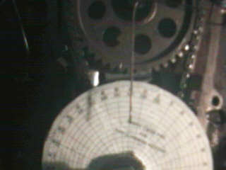
Now rotate the motor about 50 to 60 degrees off TDC and install
the piston stop.
Rotate the motor back slowly until the piston hits the stop, DO NOT
rotate fast of force the piston hard against the stop.
Record the number on the wheel. I got 18.
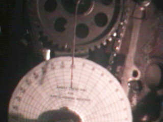
Now rotate the crank the opposite way until the piston
again hits the stop and write the number down I got 24
Now add these 2 #s together and divide by 2, 18 and 24 =42
divided by 2 = 21
While the piston is still against the stop set your degree wheel
so the pointer is on 21. rotate back the opposite way and you
should read 21 in both directions, rotate it both ways a few
times and be sure it always comes back to 21 on each side.
Your numbers may be different but works the same way
Now check it a few more times
to be sure its OK.
Now remove the piston stop and move the crank so the pointer
is on 0 zero and you have found true top dead center.
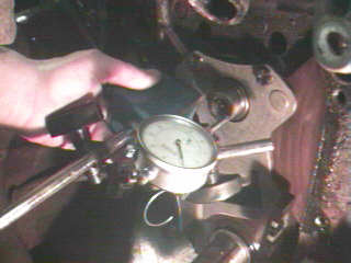
Now you will need to remove the #1 cyl intake rocker arm
but leave the push rod there, set your dial indicator so the
plunger sits in the oil hole in the push rod be sure you have
.300 to .400 preload on the indicator. and as straight a shot
as possible.
The webcam on my laptop stopped working at this point and
was unable to get any pics of the indicator set up but the
magnetic base was sitting on the headers and against the head.
Now rotate on the base circle you should be on it if you followed
everything upto this point. you should be at TDC compression stroke
both valves closed. You should have no more than .001 to .002
runout on the base circle, if its a new cam and you have more
runout than that contact the manufacture and get a new cam
it was ground off center.
Rotate a few times and be sure the indicator always returns to 0
If a stock cam rotate and set the base circle so it is equal on
both sides of 0 if you have more than .002 runout on the base
circle.
Now rotate the motor slowly and find Max lift and reset the dial to 0
Rotate clockwise the same as motor turns slowly until you hit .050
Record the number on the wheel, keep going in the same direction
slowly you will pass 0 and when you hit .050 record the number on
the wheel, if you pass it up rotate back past it .300 than clockwise
again and record both sides on the wheel at .050 off Max lift.
The indicator needle will change direction after it passes Max lift
Take both the readings at .050
Add the two degree numbers together and divide by two that is
your center line
For example 104 and 120 = 224 divided by 2 = 112 is your centerline.
If not where you want it you need to advance or retard the cam using
an offset key
You have found your centerline location. We used a 2 degree offset key
and ended up with the centerline on 110.5 to bring in more low end
DEGREE BY DURATION at .050 lift.
the opening and closing at .050" lift method is not affected by
the
lobe design, it is more accurate to degree this way.
This method will also verify your actual duration figures.
When checking, always turn the engine in the normal direction of
rotation
Set the indicator back to 0 on the base circle TDC compression
stroke. rotate until it hits .050 and record the number
Keep rotating the same direction watch the indicator it will reach
Max lift, record Max lift the indicator will change direction keep rotating
until you hit .050 before closing. this will tell you the duration at
.050
and when the valve opens and closes. A cam card will give you all
this info. stock cam starts to open at 8 before TDC and closes 56
before bottom center or 124 degrees after top at 0 lift don't use .050
lift to see the stock cam open close locations.
If they are off you need to advance or retard the cam.
Now with the cam set correctly you need to set your injector sync
with the wheel at TDC, set the rotor right over the dist line on
the picup plate
The stock cam has 31 degrees overlap this is when both valves
are open at the same time, a rule of thumb is to pulse half way
through the scavenging to get a balance where no fuel blows back
or is drawn out the exh.
The scavenging effect is caused by the air coming in and the exhaust
pulse pulling the exh out also some of the fuel charge pushing
what you want here is to have the injector pulse just right so
no fuel ends up flowing out during scavenging through the exh
valve.
Exhaust on any motor will pulse not just a steady flow like
a water hose caused by the other cyls firing. This inertia will
help draw the new air fuel charge in
0 to +3 on a stock cam cuts it very close so that no entering fuel
actually leaves the cyl.
Palsing to soon will blow the fuel back in to the intake and to
late will draw fuel out the exh.
Now reassemble the motor, use some silicone down on the
oil pan on the pan and in the corner where the pan meets the block
to assure a good seal. Also run a bead through the rubber seal that
goes between the cover and the pan. It is not necessary to use
silicon on new gaskets
Install the new front seal in the cover and be sure you put some
oil on the seal before assembly.
When installing the timing cover put the bottom in first on an angle
the same way you removed it than push the top back, it may be
necessary to use a small pry bar to push down on the top of
the cover to get the bolts in. You can just catch the intake to
do this but don't apply to much pressure the rest is pretty straight
forward on the reassemble all the other bolts are 17 foot pounds torque
Before you drop the air alt bracket down replace
the bypass hose and use 2 new sceww clamps its the
only wat to replace it you can not without raising
this bracket
if you have any questions just drop me an email.
*****************************************************
The whole job took 4 1/2 hours. Here are the specs for the stock cam
Duration.......intake........exhaust
....................250.............264
opens..........8 BTDC.......56 BBC
closes..........65ABC.......25 ATDC
overlap 31 degrees
lift .431
112 centerline 224 separation
Part numbers and prices
*****************************************************
P# 83507095.......Timing Chain and Sprocket Package.$62.70
P# 04483757.......Gasket, Water Pump 1992 - 03......$3.00
P# 53021057.......Gasket, Timing Chain Case.........$11.70
P# 4897297AA......Seal, Front Case 1992 - 03........$10.45
P# 53021195AA.....Tensioner, Timing Chain...........$39.95
P# 4286500........Offset Keys 1 to 5 degree's.......$31.00
P# 53008654.......Bypass Hose.......................$6.25
And 1 bandaid LOL
Larry
J&J Auto
|